Thursday, November 14, 2013

Fix Toyota Tacoma Overhead Temperature & Compass Display


If you have a Toyota Tacoma with an overhead compass and temperature display that is not working, it is most likely do to a bad soldering joint on one, or possibly both of the 510 resistors on the main circuit board. It is a relatively easy fix if you are comfortable with a soldering iron and have about 10-20 minutes.  

Fix Toyota Tacoma Overhead Temperature & Compas Display
This is what the compass and temperature gauge should look like when fixed. To remove the overhead panel, drop the sunglass holder and remove the screw on the top of the panel. The front should only be held up by clips.   

Toyota Tacoma Overhead Temperature & Compass Display Does Not Work
Once the overhead panel has been removed and disconnected, remove the three screws holding the display on to the overhead panel. The tinted black cover can then be removed by releasing the clips holding it into place. You should then see the main circuit board. 

Toyota Tacoma Temperature & Compass Display
If you look closely you should be able to see the two 510 resistors.

Toyota Tacoma Temperature & Compass Display Repair
If you take a very small pic tool or needle, and apply a little pressure to the edges of the resistors you should notice they will start to lift off the circuit board. So what you want to do is re-solder these contact points. You will need to use a very small soldering tip and be careful not to use an excessive amount of solder. I've found that silver bearing "lead free" solder is a bit trickier to work with, so if you have any lead based solder laying around you may want to use it for this repair. If you have no way of getting your hands on a soldering iron and solder, you could try using a circuit writer pen.

Hope this helps!
Jeremy @ Car Audio Tips    


Tuesday, June 11, 2013

BMW E46 Double Din Aftermarket Stereo/Indash Installation


I recently did an installation of a double din in-dash stereo into a BMW M3 (E46). The installation went very well and sounded great.

Factory BMW M3 E46 Double Din Indash Stereo
This is what the factory BMW M3 stereo looked like. 

New Parrot ASTEROID Smart Multi Media Stereo BMW E46 M3
I went with the new Parrot ASTEROID Smart multi media stereo, I was VERY IMPRESSED!!
Check out the link below for more info.

New Parrot ASTEROID Smart Multi Media Stereo BMW E46 M3
Do to the depth of this particular double din stereo, the installation will be a lot easier then installing a standar double din.

Behind Factory Stereo In BMW E46 M3
You will not have the depth to fit a standar double din stereo, unless you modify and cut some of the components that get in the way behind the factory stereo. That is why this Parrot stereo worked out so well.

Double Din Dash Kit For BMW M3 E46
You will need some parts for this installation, starting with the double din dash kit. Here are some places you can find one.

Metra 70-9003 Wire Harness
For the factory amp integration you can use the Metra 70-9003 wire harness.

Metra 40-EU10 Antenna Adapter
You will also need the Metra 40-EU10 antenna adapter in order to use the factory antenna.  

20 Foot Antenna Extension
Along with the antenna adapter you will need a 20 foot antenna extension, Metra 44-EC240
Another part you may want to take into consideration is a "Steering Wheel Control" interface.

In the trunk of the vehicle on the driver side, under the trunk liner you should find the stereo tuner. The antenna plug will be located on the top corner, you will want to disconnect it and use the EU-10 to adapt it to a universal Motorola plug.

On the bottom corner you will see the reverse 70-9003 harness, disconnect it and use the 70-9003 harness to integrate into the factory amp. You will then want to extend the wires off the 70-9003 metra harness and run all the wires up behind the new stereo, including the 20ft antenna extension that you will want to connect to the (Motorola Side) of the antenna adapter. Make sure you connect your Blue/White amp turn on wire. You will want to use the (high) speaker level outputs off the back of the new Parrot stereo and connect them to the input wires you extended from the trunk. All speaker wires should be CEA color coded for easy identification. The power wires you will need to find and connect separately using a digital multi meter.
I hope this helps!

- Jeremy's Car Audio Tips


Wednesday, June 5, 2013

2013 Volkswagen Passat Retaining Factory 3.5 AUX Plug With Aftermarket Stereo


If you're going to be upgrading the factory stereo in a 2013 Volkswagen Passat, and replacing it with an aftermarket stereo. You will typically lose functionality of the factory 3.5 AUX input in the center consol, unless you integrate it. It's pretty easy, you will want to make sure the new aftermarket stereo have a AUX input on the rear. That way you will not see any wires running to the face of the stereo. 

2013 Volkswagen Passat Retaining Factory 3.5 AUX Plug With Aftermarket Stereo

2013 Volkswagen Passat Retaining Factory 3.5 AUX Plug With Aftermarket Stereo

2013 Volkswagen Passat Retaining Factory 3.5 AUX Plug With Aftermarket Stereo
The three AUX wires should be in a blue 12 pin harness, that is part of the main factory stereo harness.

2013 Volkswagen Passat Retaining Factory 3.5 AUX Plug With Aftermarket Stereo Wiring
The wire should be:

Left Positive - Yellow
Right Positive - Gray
Ground/Common - Green

3.5 Aux Cable Wire Guide Diagram Left Positive Right Positive Ground
Once you have identified your wires in the vehicles, you will want to identify the wires in the 3.5 AUX cable you will be using. After you do that connect the wires, plug in the 3.5 AUX to the back of the new stereo and you should be good to go...
Hope This Helps!

Jeremy's Car Audio Tips

Porsche Carrera 4S Aftermarket Stereo Install Factory Amp Bypass


I recently installed an aftermarket stereo and amplifier into a 2003 Porsche Carrera 4S, it was a pretty easy install. If you are going to be working on one of these vehicles, this may help you out.

Porsche Carrera 4S Aftermarket Stereo Install Factory Amp Bypass

Porsche Carrera 4S Aftermarket Stereo Install Factory Amp Bypass
The factory amp should be located on the driver side of the storage compartment under the hood, right next to the spare tire.

Porsche Carrera 4S Factory Amplifier location Wiring Bypass
Once the spare tire is removed you should have easy access to the two 10m bolts that secure the metal braket holding the factory amp in place. I fully bypassed the factory amp and installed an aftermarket in its place.

Porsche Carrera 4S Factory Amplifier location Wiring Bypass
At the factory amp there should be 6 pairs of speaker wires, 2 pairs going to the front dash speakers, 2 pairs going to the front door speakers, and 2 pairs going to the rear speakers. There should also be a heavier gauge pair going to the factory subs if equipped. The front dash speakers, and the front door speakers should meter 2ohms each when testing the speaker wires at the factory amp. The rear speakers should meter 4ohms each. The factory subwoofers if equipped, behind the seats will typically meter 1ohm each (single voice coil). They are normally wired in parallel, so at the factory amp the pair of wires for the subs will meter 1/2 ohm. Depending on the aftermarket amp you are installing, you may need to rewire the subs in series to bring the load up to 2ohm.

This should be the wire colors-

Front Left Dash Positive - Yellow
Front Left Dash Negative - Yellow/Brown
Front Right Dash Positive - Red
Front Dash Right Negative - Red/Brown
Front Left Door Positive - Green
Front Left Door Negative - Brown/Green
Front Right Door Positive - Purple
Front Right Door Negative - Brown/Purple
Rear Left Positive - Blue
Rear Left Negative - Brown/Blue
Rear Right Positive - Blue (Pin 13-14)
Rear Right Negative - Brown/Blue

Once I had my speakers and subs all wired I ran power from the battery, which is only about 5 feet away. I Then grounded the amp, and ran my RCA's and amp turn on/stereo ground wires to the new stereo. 

Porsche Carrera 4S Factory Amplifier location Wiring Bypass
There should be a rubber grommet on the driver side firewall, where you can run your wires through.

Porsche Carrera 4S Aftermarket Stereo Install Factory Amp Bypass
Behind the factory stereo you should have a 12V constant wire on the factory stereo harness. I used that and the ground I ran from the same grounding point as the new aftermarket amp, to try and eliminate the possibility of engine noise. You will however need to run switched power from the fuse panel (driver side kick), or tap into switched power directly off the vehicles ignition switch. DO NOT MISTAKE THE VSS WIRE FOR SWITCHED POWER ON THE FACTORY STEREO HARNESS.
Hope This Helps!
Jeremy's Car Audio Tips  


Tuesday, May 28, 2013

1995-2002 Toyota 4Runner Fog Light Installation Using Factory Fog Light Prewire

I recently installed aftermarket fog lights on a 2000 Toyota 4Runner (Third Generation). I was able to use some of the factory wiring that was already ran for optional factory fog lights.

1995-2002 Toyota 4Runner Fog Light Installation Using Factory Fog Light Prewire

Fuse Relay Wire Wiring Location For Factory Fog Lights Toyota 4Runner
Under the hood on the driver side, you should be able to locate the fuse/relay panel. The fog lights fuse/relay location are normally clearly marked on the top plastic cover. 

Fuse Relay Wire Wiring Location For Factory Fog Lights Toyota 4Runner
The fog light circuit is typically fused at 15 amps. If the vehicle didn't come equipped with the factory fog lights, there will most likely be no relay in the location. If you look at the relay location you will notice five female spade connectors. The two larger spade connectors on the right side are the ones I used (A and B. One should meter constant 12V, the other should meter continuity to the pink wires on the factory fog light harnesses.

Fuse Relay Wire Wiring Location For Factory Fog Lights Toyota 4Runner
The factory fog light harnesses should be taped up behind the bumper. On each side, they are pretty easy to find.

Fuse Relay Wire Wiring Location For Factory Fog Lights Toyota 4Runner
On the factory fog light harnesses you should have two wires
White/Black - Ground
Pink - Goes up to fuse/relay panel in engine bay (Positive)

1995-2002 Toyota 4Runner Fog Light Installation Using Factory Fog Light Prewire
If you connect your aftermarket fog lights, to the wires at the factory fog light harnesses. White/Black wires should connect to ground wires coming off the aftermarket lights, Pink wires should be connected to the positive wires coming off the aftermarket lights. Now when you jump terminals A and B at the factory fog light relay location, you should be able to power up your new fog lights. The fog lights I installed required about 8 amps of current with the vehicle off.

1995 1996 1997 1998 1999 2000 2001 2002 Toyota 4Runner Fog Light Installation Using Factory Fog Light Prewire
Now all I did was run two wires one from terminal A and one from terminal B, though the fire wall into the vehicle and connected them to an on/off switch.
  
1995 1996 1997 1998 1999 2000 2001 2002 Toyota 4Runner Fog Light Installation Using Factory Fog Light Prewire Wiring
You will always want to make sure to use a switch that is appropriately rated for this application. If I remember correctly I used a switch rated to handle 25 amps @12 Volts.
 Hope this helps!

Jeremy's Car Audio Tips    

Tuesday, May 21, 2013

Volvo XC90 Aftermarket Stereo Installation


If you haven't installed an aftermarket stereo into a Volvo XC90, then you may find this car audio tip helpful.

Installing New Aftermarket Stereo In Volvo XC90

Installing Aftermarket Stereo In Volvo XC90
The stereo removal is pretty easy if you need step by step direction for removal I will post a link bellow.
Along with a dash kit, you will also need an aftermarket antenna if you want to be able to get reception with your new aftermarket stereo. I will post a link to the antenna I typically use bellow.
If your going to be integrating the factory steering wheel controls you will also need a SWC interface, like the one bellow.

Installing Aftermarket Stereo In Volvo XC90
Moving on, once the stereo/ac control panel is removed you will need to separate the face of the stereo from everything els. Make sure the key is completely out of the ignition switch before disconnecting any wire harnesses. Do not place the key back into the ignition switch until you have reconnected all necessary harnesses. 

Installing Aftermarket Stereo In Volvo XC90
The main LCD display will need to be reconnected and remain in the vehicle to allow the factory components to function properly. In order to make this possible you will first need to remove the LCD display from the stereo panel. 

How To Install Aftermarket Stereo In Volvo XC90

How To Install Aftermarket Stereo In Volvo XC90
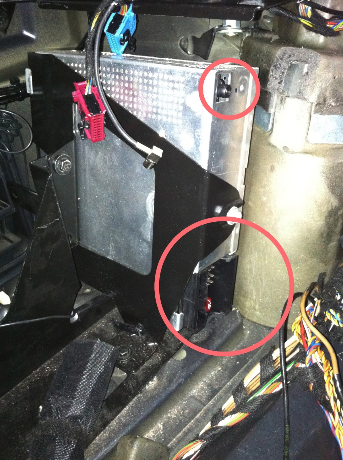
The CD changer portion of the stereo can be removed, and will no longer be used. The main LCD will need to be reconnected and set aside.

Aftermarket Stereo Installation In Volvo XC90 Power Wires
This is the CD changer harness. Other than the two orange fiber optics cables there should be three wires.
12V Constant - Violet/White 
Switched 12V - Violet
Ground - Brown
When I wired up the new stereo harness I tapped into the Violet/White for my 12V Constant at this harness, but I tapped into the cigarette outlet power for my Switched 12V and ground because I know the cigarette outlet is rated for more current.

Aftermarket Stereo Installation In Volvo XC90 Power Wires
The wires coming off the cigarette outlet harness should be,
Switched 12V - Violet
Ground - Black 

Aftermarket Stereo Installation In Volvo XC90 Factory Amp Bypass Speaker Wire Colors
Once you have connected your main power wires for your stereo, and any accessories like the power antenna, SWC interface, you will need to connect your speakers. The Volvo XC90 I installed this stereo in had what was called the eight speaker system. Some will come with the twelve speaker system, with an optional sub. If the vehicle your installing the new stereo in has the twelve speaker system you will need an additional amp to power the additional speakers. Otherwise some speakers will be lost including the factory sub. 
The speaker wires can be found back bellow where the factory stereo/ac controls mount, in the dash.
Front Left Positive - Gray/Red
Front Left Negative - Gray
Front Right Positive - Gray/Red
Front Right Negative - Gray
Rear Left Positive - Gray/White
Rear Left Negative - Gray
Rear Right Positive - Gray/White
Rear Right Negative - Gray
As you can see you will need to meter and pop the speakers with a 1.5V battery to identify what side the speaker is on.

Aftermarket Stereo Installation In Volvo XC90 Factory Amp Bypass
 After locating the speaker wires you will want to cut each pair. One side will be coming from the factory amp, the other side will be going to each set of speakers. You shouldn't need to use the side that runs down towards the factory amp under the passenger seat. The other side should be the side that runs to each set of speakers, you will want to test this side with a digital multi meter. You should get a reading of around 2ohms on each pair of speaker wires. Now depending on the stereo your installing, will depend on how you will want to wire these factory speaker to your new stereo. If your new stereo doesn't support 2ohm speakers, then you may need to wire the front left and rear left speakers in series and the front right and rear right speakers in series to get the impedance up to around 4ohms. You will lose your "Fade" in the stereos settings, along with some volume and quality but should allow you to power the factory speakers off the aftermarket stereo without adding an aftermarket amp. If you are also installing new speakers then you shouldn't have to worry about the impedance of the factory speakers.

Aftermarket Stereo Install In Volvo XC90
After you have all your wiring taken care of, you will want to place and secure the main LCD nicely bellow the stereo. I normally rap it in carpet.

Aftermarket Stereo Install In Volvo XC90
That's just about it, sometimes you will have to cut out some of the plastic behind the stereo to get it to fit in just right. One other thing you may want to be aware of is the headphone controls in the back of the vehicle will be lost. 

Volvo XC90 Air Bag Light Reset Autel AutoLink AL619 Tool

Volvo XC90 Air Bag Light Reset Autel AutoLink AL619 Tool
If you happend to trigger the AIR BAG LIGHT then you will need to get that code deleted at the dealership, or if you want to do it yourself you can purchase a diagnostics tool like this. 
It is the Autel AutoLink AL619
Anyway I hope this helps!

- JEREMY'S Car Audio Tips


Ford F-Series Super Duty Trucks - Wiring Factory Auxiliary Upfitter Switches


If you are looking to use the factory upfitter switches in a Ford F-Series Super Duty Truck (F-150, F250, F350, F450, F550) then this tip may be helpful to you. 

Ford F150 F250 F350 F450 F550 Super Duty Factory Upfitter AUX Switches
The 4 factory switches are typically located on the lower passenger side of the dash, below the stereo.
 They can be used to power and control additional accessories, when the vehicles ignition switch is in the on position.  

Ford F-Series Super Duty Factory Upfitter AUX Switch Wiring Location
The auxiliary upfitter switch wires aren't typically the wires you will clearly see right bellow the driver side steering column. 
You can typically find the wires and the relays under the plastic cover, located on the end of the driver side dash.

Ford Super Duty Factory Wiring And Relay Location For AUX Switches
Once that cover is removed, you should see the black relay pack. 

Ford F-Series Truck Factory Wiring And Relay Location For AUX Switches
You can remove the black cover to reveal the 4 auxiliary switch relays. The output wires will be located below the relay pack, coming out of factory black split loom. 


Wiring Location For AUX Switches Ford F-Series Truck
 Near the output wires, you should see a white tag that identifies the aux output wire colors with the aux switch number. 

AUX 1 - Yellow
AUX 2 - Green/Brown
AUX 3 - Violet/Green
AUX 4 - Brown 

You should be able to located the fuses for the auxiliary switches in the fuse panel to identify the max current for each switch. I believe AUX 1-2 are 30 Amps, and AUX 3-4 are 10 Amps.

Wiring Location For AUX Switches Ford F-Series Truck
If you need more room to work, you can unclip the relay pack and pull it out under the driver steering column right near the parking brake.

Wiring Location And Color For Factory AUX Switches Ford F-Series Truck
You can also then gain access to the wiring off the back of each auxiliary relay.
Hope this helps!

- JEREMY
Car Audio Tips